MY BSA A65 NEEDLE ROLLER BEARING
CONVERSION
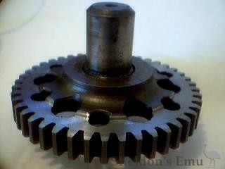
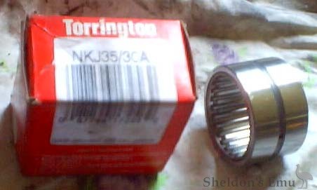
My A65 is an early motor with a ball bearing on the drive side. The whole bike is a bitser so I decided to do a bit of experimenting. I thought seeing as the ball bearing locks the drive side a plain needle roller bearing would be sufficient for the timing side. The bearing is a Torrington NKJ 35/30A OD 50mm ID 35mm W 30mm. In the picture the inner sleeve is missing. The crankcase was machined all the way through and the bearing received 1.5 thou. interference . This bearing is not C3 tolerance so I polished 1.5 thou off the OD of the inner sleeve [not the right thing to do]. A bearing with C3 tolerance would be better and is recommended.
 BSA-A65-NRC-0
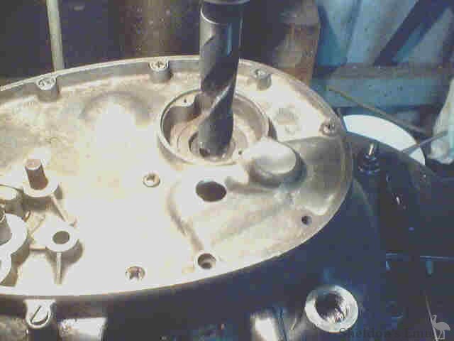
I don't like the idea of the bearing surviving on splash alone so I have extended the return oil gallery back to the edge of the main bearing and drilled into it a 1mm hole. my reasoning is that when fit an oil filter in the return line it will create back pressure and give the bearing a squirt of oil.
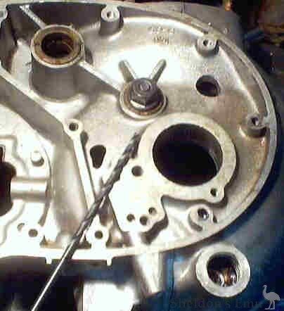
A 3/16" long series drill is used and the depth of the hole is 98mm.
The return gallery passes through the oil pump stud hole at a depth of 13mm to the centre of the oil gallery measured from the oil pump face.
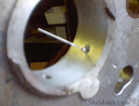
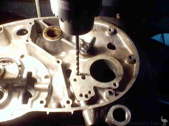
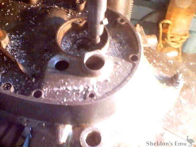
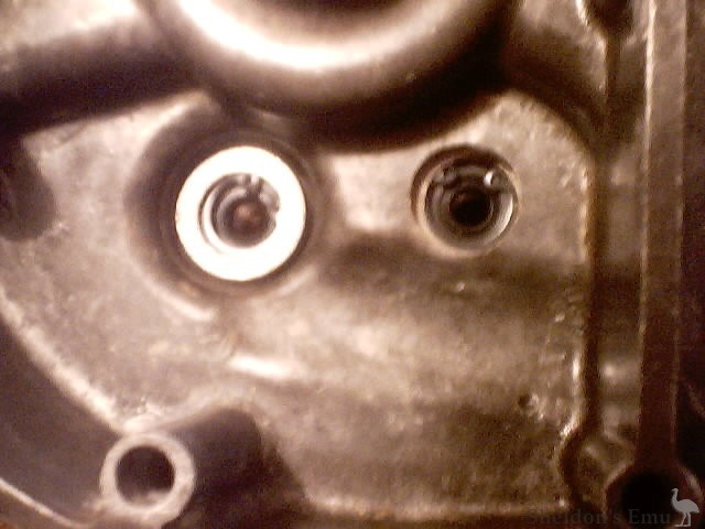
Sorry about the pic quality on this one. I drilled a 1/4" hole about 1/4"
deep 13mm down from the oil pump face and then drilled the 1mm hole into the return gallery. The hole at
the bottom without the drill in it is the original feed hole to the bronze bush. This hole must be
plugged to prevent loss of pressure as it coincides with the oil groove in the N/R bearing. I machined a
small alloy plug that was an interference fit with the hole and hammered it home with a punch and
locktite. It only needs to be about 4 mm thick as you do not want to block the oil gallery below to the
pressure relief valve.
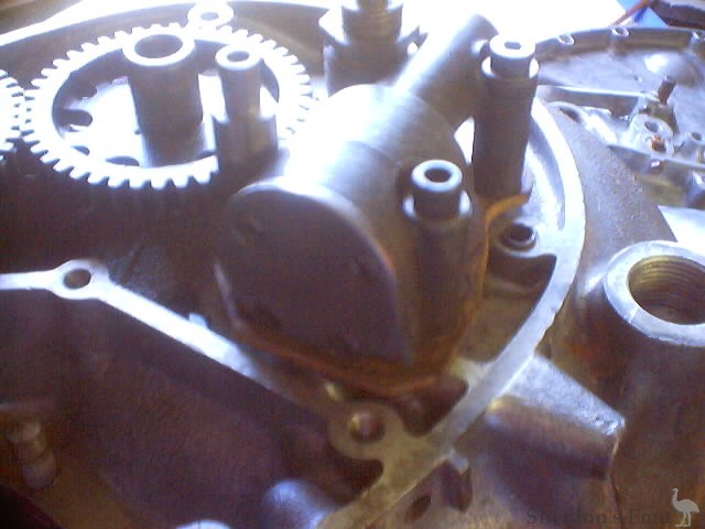
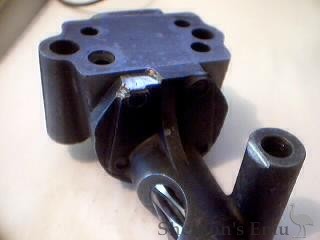
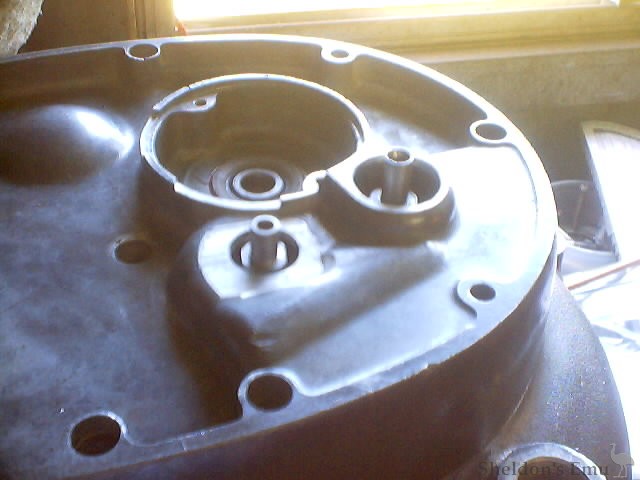
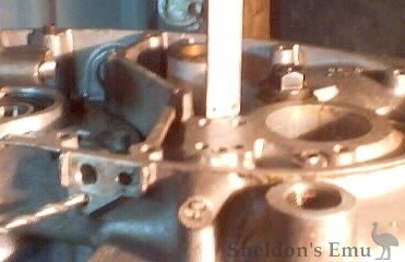
Above is a pic of the oil pump in which I have drilled a hole from the feed side of the
pump into the top stud hole. Below is another view of it. The idea is to split the oil in the pump and
send it out through a special quill bolt to a fabricated block welded to the inner cover and through a
hollow bolt to another welded block and then into the crank quill.
The oil pump stud hole is drilled to 8mm to accommodate the larger quill bolt. The centre of the
splitting oil hole is 15mm from the top of the stud hole.
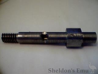
The total length of the quill bolt is 66 mm, the threaded portion is12mm and from there to the 1st
step is 33mm.The next section is 10mm long, with a 13mm OD and 4flats filed in it. The next section
is11mm long and 8mm OD. This section goes into the oil seal which is 8mm ID 16mm OD and 7mm W. The hole
filed in the quill bolt is 15 mm down from the 1st step. To find the correct position, you first fit a
3mm thick cork gasket (this holds the pump clear of the N/R bearing that protrudes through the
hole into the oil pump face) and then the oil pump. Fit the 2 cap head bolts and the quill bolt with a
small gasket washer. Tighten all bolts then mark [centre punch] the quill bolt on the side that faces
the splitter hole in the oil pump insuring a good alignment when fitted, then file hole.
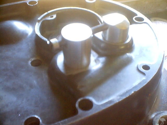
The quill bolt and 3mm cork gasket can be seen in this pic. Also note that the forward oil pump bolt
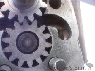
has had the head machined down to the same height as the rear so the inner cover can be fitted. I had to
machine 2mm off of the back of the idler gear to clear the bearing because
used a later crank in an early motor which we all know is 1mm wider [ I FORGOT DUH!!] I also had to
machine down the inside of the cases where the mounds prevent the original bush from turning by 2mm. The
oil pump was also touched up for this reason, see pic. If the proper crank for that year had
been fitted I believe would not have had to do those things.
However on the bright side I now know that later cranks can be fitted to early motors
;>)
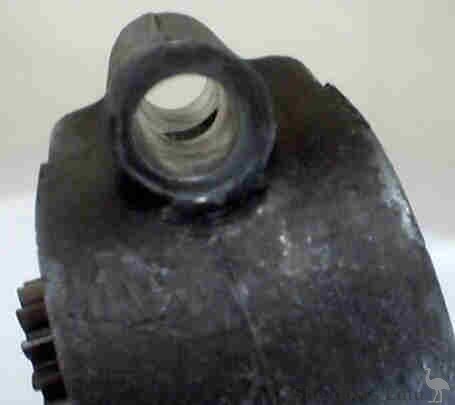
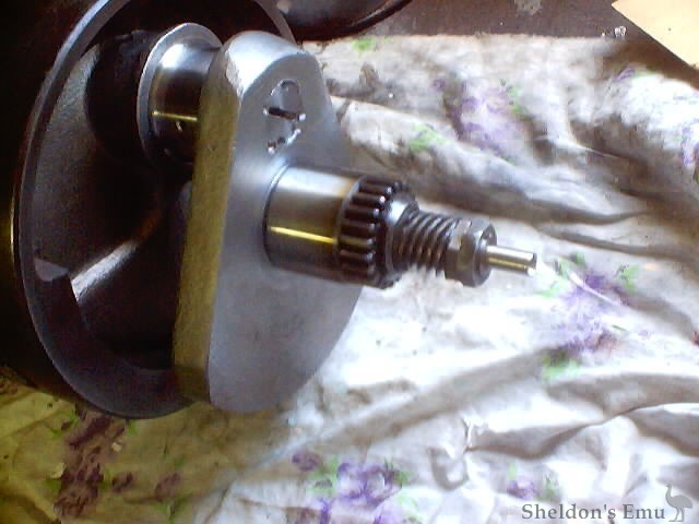
This is a pic of the crank after grinding. I machined the inner bearing down so it was held firm by
the back of the gear when it was pushed fully home. The quill is stainless and finally machined to 8 mm
OD. Note slight bluing on the end of the bearing. This was caused by machining with a carbide tool DUH
should have taken the time to grind it.
Now the inner cover and finding the oil block positions. First machined
the 2 areas where they were to go flat. Then set up on the oil pump fixing stud hole.
Next fit the inner cover and change to a 3/4 " drill bit.
Next dial up the crank shaft bearing hole and refit the inner cover. This time boring to 1"
This pic shows the inner cover fitted with the oil pump quill bolt and the crank quill showing.
This pic shows oil seal holders and hollow bolt that carries oil from oil pump quill bolt to crank
quill. I machined two steel inserts the size of the oil seals and fitted them in the holders to locate
them in the correct position while they were welded. After welding they were removed and the oil seals
fitted with circlips to hold the seals in place.
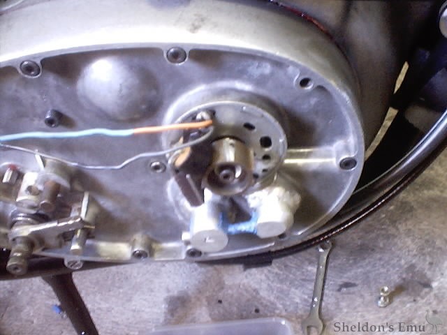
This pic is it fitted to bike. Note that I had to shape the seal holder that fitted
over the crank quill so it would not foul the outer cover. This was done prior to welding.
With hindsight I would use a bearing with a 55mm OD and a 20 mm width. This would
allow a std gasket thickness to be used under the oil pump.
Well That's It. HTH