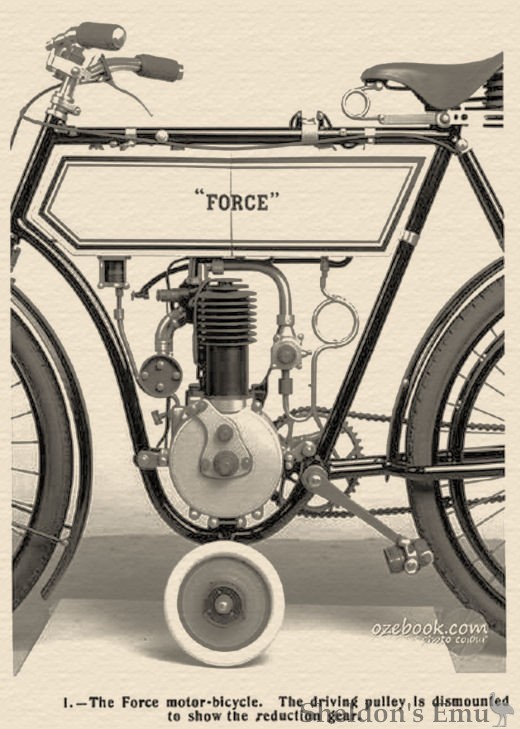
The Woolliscroft firm built a "Force" motorcycle in 1903.
"Woolliscroft Motor Company (Limited), 177-179, Foleshill
Road, Coventry.– Capital, £30,000 in £1 shares. The first directors
are W. A. Taylor, W. W. Woolliscroft, L.R.C.P., M.R.C.S., and
F. C. Colliard. "
~Automotive Journal, 1903, via Archive.org
"Force Motor Syndicate
1902 Registered with directors William Allen Taylor, Charles Ernest Warren and Frederick Ernest Woolliscroft"
~Graces Guide.
HEREWITH we give an illustration of the new motor-bicycle, known as the "Force," which has lately been put on the market by the Woolliscroft Motor Company, Limited, of Coventry. The main point kept in view in the machine has been simplicity in design, with the idea of reducing cost of production to a minimum, consistent with reliability and efficiency. Endeavour has also been made to render control so easy that any ordinary cyclist can manipulate the machine on his first ride. The machine is of the loop frame type, a 2-h.p. motor being carried in a vertical. position, low in the frame, so as to obviate sideslip and give greater tank capacity. Although the battery and coil are both fitted in compartments in the single tank employed, the petrol capacity is just over 1 1/3 gallons.
The cylinder dimensions are 70 mm. by 70 mm., the engine developing 2-h.p. at a speed of 1,000 revolutions per minute. Simplicity of control is obtained by connecting a switch arrangement to the handle-bar lever, which also actuates the exhaust valve lifter, thus the movement of two fingers of the right hand is sufficient to at all times control the engine, while the objectionable exhaust-box explosions which sometimes follow the lifting of the exhaust valve are rendered impossible, as one cannot raise the exhaust valve without at the same time interrupting the electrical circuit. The attachment of the motor to the frame is by means of a strong hinge lug in the bottom of the loop, and the vertical position is normally maintained by means of a pair of clamp plates which firmly tie the crank case to the bottom bracket and the front portion of the loop respectively. When the bolts holding these clamp plates are slackened, the latter, being each slotted at one end, may be detached hookwise from the frame lugs, thus rendering it possible to swing the engine sideways to an angle which facilitates access to the valve chamber, etc.
A novel driving gear system is employed, which it is claimed presents an unique combination of advantages. The belt pulley is not, as usual, fitted to the crank shaft, but its place is taken by a small steel pinion. This in turn meshes with a toothed wheel twice its diameter, the latter being securely fastened to the interior of a belt pulley double the size of those generally used to obtain a corresponding ratio of gear. The advantage claimed for the arrangement is that it more than doubles the grip between belt and pulley. The belt pulley is centred on a stud carried by an adjustable quadrant, which is provided with a milled headed screw, rendering the tightening of the belt a similar operation to that performed in tightening the chain on an ordinary bicycle.
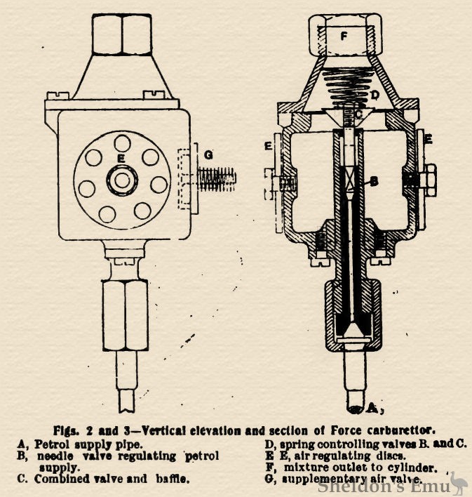
The automatic carburettor used in connection with the machine, shown in Figs. 2 and 3, is claimed to give a perfect working mixture for any engine speed. This is effected by setting the discs EE to give sufficient air for a good reliable starting mixture. The supplementary air valve G remains closed until the engine attains a certain speed, when it commences to open, admitting an increasing proportion of air to the mixture as the engine speed rises; thus it obviates the necessity for the rider to interfere with the carburettor, while it renders a carburettor lever on the frame tube unnecessary, the only lever so furnished being that which advances or retards the ignition. The petrol enters by the pipe A, and on the suction stroke of the motor the valve C is lifted against the action of the spring D, spirit being drawn in past the needle valve B. As regards the lubrication, a small compartment is partitioned off at the forward end of the tank. Underneath this compartment is a small transparent lubricator, which is filled by a movement of a small lever on the top of the tank, and within easy reach of the rider. A reversal of this lever cuts off the supply from the tank, and at the same time opens the connection to the crank case, whence it is rapidly drawn by the suction of the piston.
Derived from images supplied by Murray Barnard. Original source unknown, but possibly from The Autocar.